
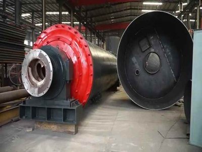
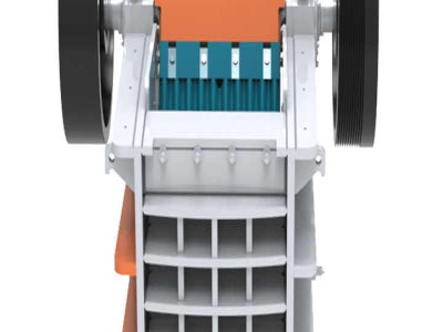
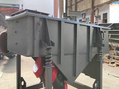
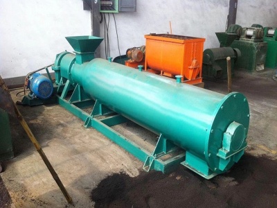
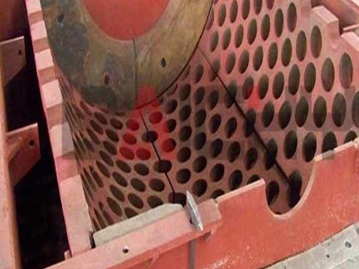
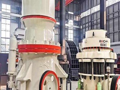
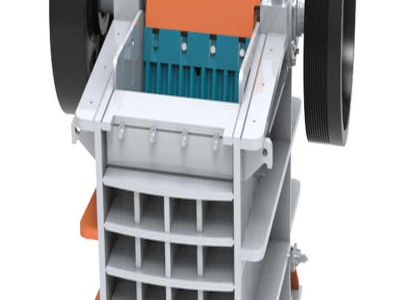
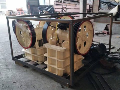
block logic diagram of conecrusher
![Block Diagram []](/60p84f3/1398.jpg)
![Block Diagram []](/60p84f3/47.jpg)

Fuzzy logic speed control of an induction motor
Fuzzy logic speed control of an induction motor ... of the controller block A using fuzzy logic. ... The user can build block diagram models with click ...
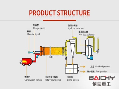
ICT81A Block Diagram LOGIC ICOM Incorporated
Block diagram details for FCC ID AFJICT81A made by ICOM Incorporated. Document Includes Block Diagram LOGIC.


3: Logic Circuits, Boolean Algebra, and Truth .
Truth Tables 2. Logic Circuit Diagram 3. ... 18 Responses to "3: Logic Circuits, Boolean Algebra, and Truth Tables ...

SIMATIC Function Block Diagram (FBD) for S7300 and .
• Ladder Logic (LAD)/Function Block Diagram (FBD)/Statement List (STL) for S7300/400 manuals • Standard and System Functions for S7300/400
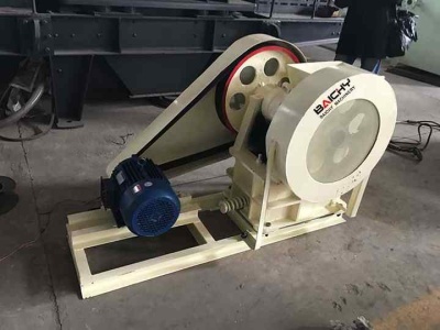
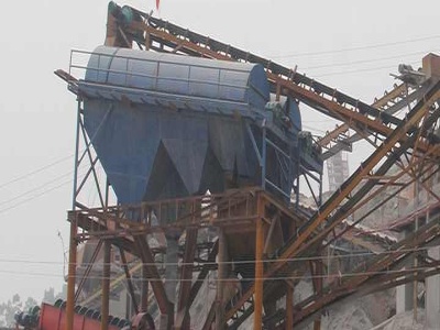
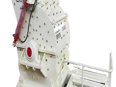
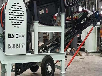
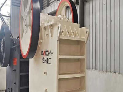
Detailed Drawings For Manufacturing Crushers
file engineering drawings of jaw crusher pdf cone crushers . we ... 2d drawings block machine,block crusher ... diagram of conveyor belt ...


PLC ( Programmable Logic Controller ) : .
Block diagram of PLC. Block diagram of PLC Programmable logic controller. PLC contains mainly three unit CPU, INPUT and OUTPUT. CPU:CPU contains a processor. CPU read and executes programming instruction which is programmed by programmer. CPU controls all activity by receiving input, and as per program control all output.

Computer Logic Wikiversity
Computer logic is an aspect of computer design concerning the fundamental ... Block diagrams are used so that somebody looking at a circuit ...
Create Block Diagram | Logic Block Diagram .
Block diagrams solution extends ConceptDraw PRO software with templates, samples and libraries of vector stencils for creating the block diagram. ...
Basics of Simulink TUM
hierarchical block diagrams ... Basics of Simulink ... use diagrams to implement modal logic, ...
Patent US Method of using .
1. A method of using block diagram to combine logic expressions, the method comprising the steps of:

Draw a logic diagram for a full adder Give a .
Draw a logic diagram for a full adder Give a block diagram of a 4 bit adder from CS 260 at Washington University in St. Louis


Figure 91 Block Diagram of Static RAM Table 91 Truth ...
Figure 91 Block Diagram of Static RAM Table 91 Truth Table for Static RAM ... use _logic_; ... Figure 98 Block Diagram of RAM System

Design of Half Subtractor(Block Diagram,Truth .
· In this tutorial we have completely explained the design of half subtractor block diagram,Truth Table,K map and Logic circuits. Combinational ...

Converting State Diagrams to Logic Circuits
When a clock pulse occurs, it moves us into period 2. Looking at our state diagram, we see that the only thing that moves us out of State 1 is if the user presses the button. When the clock rises between period 1 and 2, the button is released, therefore we stay in State 1. The bulb is still off.

ControlLogix /RSLogix 5000 Rockwell Automation
to efficiently program a Logix5000 controller using function block diagrams. ... ControlLogix ® /RSLogix 5000. ... Ladder Logic. course ...
Function block diagrams | Control Engineering
· Functions, function block diagrams. A function is a software element that, when executed with a particular set of input values, produces one primary result and does not have any internal storage. Functions are often confused with function blocks, which have internal storage and may have multiple outputs.
Function Block DiagramDigital Logic Design .
Function Block Diagram The flexibility of custom block creation is enhanced by the fact that the user can build custom blocks using ladder diagrams or any of the other IEC 11313 languages (IL and ST). Also, custom blocks can be used in conjunction with other standard or vendorspecified function blocks.
Chapter 2: Drawings and Diagrams | .
home reference library technical articles electrical and electronics chapter 2: drawings and diagrams ... block diagrams. ... programmable logic ...
Block Diagram Of Fuzzy Logic Controller – .
Block Diagram Of Fuzzy Logic Controller allowed to help my weblog, in this particular time period I am going to demonstrate regarding Block Diagram Of .